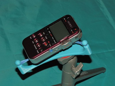
3D Printable shock mount for PCM-M10 digital recorder

PCM-M10 Shock Mount

PCM-M10 Shock Mount

Several years ago I played with a lot of audio stuff including making binaural recordings of things like cicadas, train rides, and festivals in Japan, and the singing of tree frogs in my back yard when I lived in a forest in Missouri.  Those recordings were done on a MiniDisc recorder because it was the best available audio quality recorder for people on a budget (i.e. cheapskates) like me.   Time and technology wait for no one, and I’ve been getting the itch to do some recording again, so I recently picked up a Sony PCM-M10 recorder.   This little machine records in many different formats up to and including 24 bit/96 ksps (though self-noise really limits the machine to about 15 actual bits).  The audio is recorded onto micro SD cards so unlike the MiniDisc, you get access to the raw digital data without any compression or associated quality degradation.

My previous recordings were done using a DIY binaural microphone that used a roughly matched pair of electret condenser mic capsules mounted on a wire bail that held the capsules inside my ears.  Even though those mic capsules were pretty noisy, the recordings came out pretty good.  When you listen to them with headphones you get a real “you-are-there”, surround-sound experience that can be quite startling.  You can hear those recordings here: http://mark.rehorst.com/Binaural_Recordings/index.html   Soon, I’ll be starting a new binaural mic project to go with the new recorder, this time using much higher quality mic capsules.

In the meantime I was looking for a shock mount to use when making recordings using the built in mics.  The shock mount prevents low frequency noise from handling, bumping the table the recorder sits on, etc., from being coupled to the mics through the body of the recorder.  I did a web search and found only a couple unsatisfactory designs so I did what any maker would do- I made!

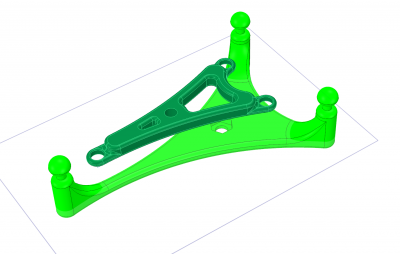
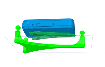
One of the flaws in the few designs I saw was that some of the numerous switches and I/O jacks on the recorder would not be accessible when it was bolted to the shock mount.  They also didn’t look very nice.  After a lot of sketching possible designs on a whiteboard and paring the thing down to a minimal implementation, and spending much too much time making a 3D model of the recorder, I came up with a printable 3-finger design that holds the recorder either on a tabletop or a tripod and keeps ALL the switches and I/Os available.  The only thing you can’t do while the recorder is mounted is swap batteries (but with 40 hours record time on a set of two AAs, that shouldn’t be a problem).

I used DesignSpark Mechanical to make the recorder model and design the shock mount.  DesignSpark makes rounding corners of complex 3D objects easy (nearly impossible in Sketchup), but I did run into some of its limitations that I hadn’t previously considered.  One huge limitation is that there is no way to put any form of text into a drawing without some special work-arounds (use Sketchup to make text, then import into DesignSpark).

CAD drawing of shock mount

CAD drawing of shock mount

PCM-M10 on shock mount- CAD

PCM-M10 on shock mount- CAD

This shock mount design is available here:  http://www.thingi

verse.com/thing:384567


I printed the shock mount on MegaMax using Coex3D Aqua ABS filament.
 

PVC Musical Headboard Build

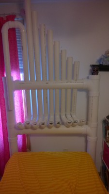
5 years old have many things in common. A penchant for poor personal volume control, meth-addict levels of energy, and an OCD like compulsion to make noise. Mine in particular has the “drummer” variant of that condition and so loves to bang on anything and everything. This affliction made manifest is the Blue Man Group, naturally his favorite musical group. So when he needed a new headboard for his bed, we decided to see what we could do let him exercise his inner Blue Man.

Materials were:

  •  4 pieces of  6’  long, 4 inch PVC
  •  4 pieces of 10’ long of 2 inch PVC.
  • 2 & ½ bags of 2 inch 90 degree elbows
  • You’ll eventually need PVC primer and glue as well once you’re ready to lock everything in place.
  • 2 3/8” hole drill bit. (Exterior diameter of 2 inch PVC is 2 3/8)

The math behind the right lengths for the right tones are pretty straight forward – I just followed the recommendation from a PVC instrument instructable by tallman1996 – there he explains:

“I got an equation from nate true that will give you the length of the pipe you need when you plug in the frequency: Tube Length (in) = (13300/(2*Frequency))+(Tube Diameter/2)

For the frequencies of the notes in the range of the piano go here: http://en.wikipedia.org/wiki/Piano_key_frequencies
My low note was number 16 (C2) in the list on the wikipedia page.”

WP_20140209_09_59_01_Pro

Drilling the holes through the 4 inch pipe was easy, just lay two parallel lines opposite each other on either side of the pipe and mark your drill holes on either side at equal distances from one end. The 2 3/8 hole bit went through easily but you had to keep it completely perpendicular to the pipe or it would jam. I highly recommend you use a drill with a torque setting so you don’t snap your wrist or have the pipe turn and crack you in the head when it jams. Don’t ask me how I know this.

Also, PVC power / flecks have amazing static cling powers so be aware that it’s rather messy.

Since I was worried about the pipe length hitting the ceiling and didn’t want a spaghetti mess of pipes on it I opted for a C3-C4 whole note scale with an extra C2 at the bottom for a nice low note.

It turned out well, we need to paint and glue the PVC together and drill the elbows to the lower cross member but even with the dry fit they stay together pretty well. With the 90 degree elbow on the end, he could continue to stick pipes on it and change or add notes if he’d like.

Paddles for now are just a pair of old flip-flops that will be modified to have handles. Any dense foam rubber will do.

This was also a great excuse to try out my new GoPro 3 on Time Lapse, so here is a video I did of the build:


2014 RPM Challenge: Accepted!

Today is the first day the 2014 RPM Challenge, which is the National Novel Writing Month of music!  The goal of the RPM challenge is to compose and record an entire album during the month of February! I accepted the challenge by dusting off my Cacophonator and Mohogonator, and got to work making music after dinner today. As today also marks the 50th anniversary of the Beatles invasion, this project drew inspiration from the Beatles’ back catalog!

RPM_Challenge

I used the dynamic duo of Cacophonator and Mohogonator with Auditionator (i.e. Adobe Audition) to record a session for about 12 minutes at a blazing fast 192kHz sample rate.  After chopping the recording into individual tracks, I digitally slowed them down to the customary rate of 44.1kHz, thereby expanding the work to its final ~45 minute length.  For inspiration while I was recording, I listened to Beatles songs sped up to 435% (which is 192/44.1) of their customary speed.  My tracks needed a bit of post-processing: on some of them I chose to bump the pitch back up an octave or two and add “Beatle Fades” to the beginning and end.  Anyway, within twenty minutes after the recording was made, I had edited the songs and uploaded them.  You’ve read that correctly, in less time than it takes to listen to the pieces, they were composed, recorded, processed, mastered, named and uploaded.

Today is also the 50th anniversary of the first Beatles song hitting #1 on the US pop charts: “I Wanna Hold Your Hand.” This whole project was inspired by this apparent coincidence in timing, and each track was directly inspired by listening to the sped-up Beatles original.  I hope you enjoy each of the 11 tracks I created!

While My Cacophonator Gently Weeps
Got To Get You Into My Cacophonator
All You Need Is Cacophony
With A Little Help From My Cacophonator
Sgt. Cacophonator’s Lonely Hearts Club Band
Cacophonator Came In Through The Bathroom Window
Lucy In The Cacophonator With Diamonds
Got To Get Cacophonator Into My Life
A Hard Day’s Cacophonation
You’ve Got To Hide Your Cacophonator Away
Cacophonator Wants to Hold Your Hand

It may be more convenient to listen to the entire album: “Cacophonator 2: Electric Boogaloo; A Love Tragedy in 11 Parts” on the RPM Challenge site’s Cacophonator page. Just scroll down to “My Player.”  There is plenty of February left: I encourage everyone to participate!

The Milwaukee Makerspace Theater

BIG_HMMMMMM2

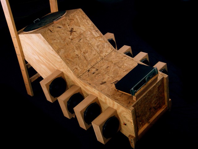
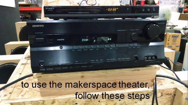
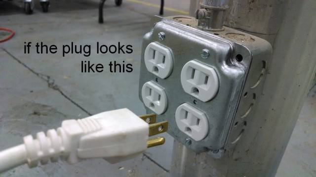
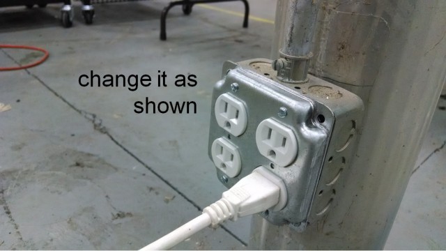
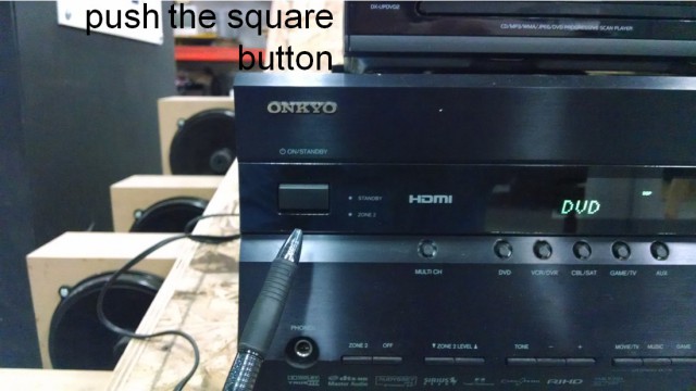
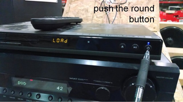
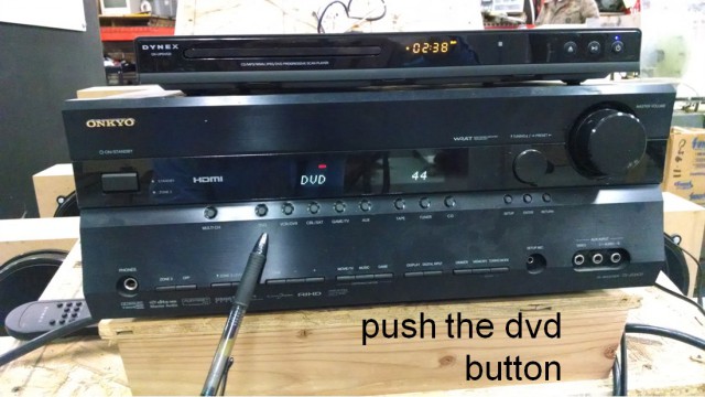
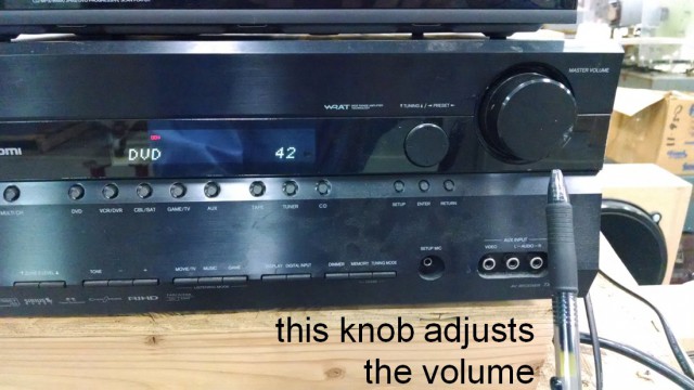
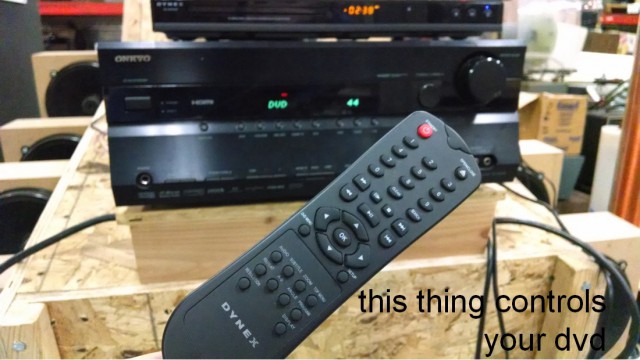
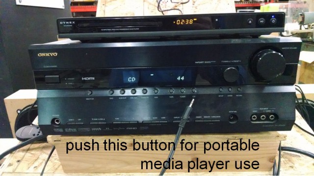
Around 25 members have hopped in the new Milwaukee Makerspace Theater after the last two Tuesday meetings.  Its up and running in a “no hearing protection required” way!  The bass still goes way down to subsonic tones, but its being powered by a small & sensible surround sound amp.   Its a very immersive audio experience, and likely sounds much better than any 5.1 system you’ve heard because there’s only one seat!  The sound has been optimized for the single theater-goer: You!  The theater is hooked up to a DVD player, and is available 24/7  for any member to watch a movie in: no check-out required.   Note that any video source you have can be hooked up via the HDMI cable.  Alternately, you can follow the lead of JasonH, who used the theater with a portable audio player to rock out while he worked on his own project near by. See the photos below for the simple instructions on how you can start up the theater, and feel free to take a break from making by using the theater!

123456789

Laser Cutter Venting System, Version 5.0

Sometimes solving one problem creates a few new ones! As part of the Laser Cutter Room Reconfiguration, the exhaust system got an upgrade. A new, bigger, more powerful fan meant we needed a new way to control it. The previous system (Version 4.0) was a simple on/off switch. That just wasn’t going to cut it for this industrial grade blower. Tom G., Tony W., myself and others spent the holidays installing this new two-horsepower beast above the ceiling in the Craft Lab. Once it was hung from the roof joists with care, Tom got to work ducting it over to the Laser Cutter Room. Finally, when all the heavy lifting had been done and the motor drive had been wired up, all we needed was an enclosure for the switch.

The request went out on the message board. Pete P., Shane T., and I all expressed interest, but life got in the way and it soon became a matter of whomever got to it first would be the one to make it. I ended up devoting the better part of last weekend to this project (much more time than I anticipated) but I can honestly say I’m pretty happy with the result.

LCEC01

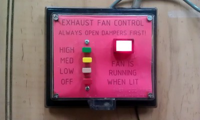
The goal was fairly straight-forward: make an enclosure for the switch Tom had already provided. It was a color-coded, 4-button, mechanical switch that had been wired to provide four settings: OFF, LOW, MEDIUM, and HIGH. The more laser cutters in use, the more air you’d need and the higher the setting you should choose. There’s four duct connections available for the three laser cutters we currently have.

There’s a saying: “Better is the enemy of done.” Truer words have never been spoken in a makerspace.

At first I wanted to build the enclosure out of acrylic. Then I remembered this awesome plastic bending technique that Tony W. and some others told me about. I found a video on the Tested website and got inspired. (If you don’t know about Tested, please go check it out. You’ll thank me later.) Unfortunately, my bends kept breaking and melting through, so after a few hours of tinkering I moved on.

Thankfully, we have a small cache of plastic and metal project enclosures on our our Hack Rack. I managed to find a clear plastic, vandal-proof thermostat guard. It looked workable.

I tried laser cutting it, but the moment I saw the plastic yellow and smoke, I knew there was probably some nasty, toxic stuff in it, so I moved to the CNC router. About an hour later I had my holes cut.

Then came the wiring. Up until this point I had been focused on the control box itself. Now I wanted to add a light!

No, two lights! Yeah!

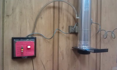
One light to tell you when everything was off, and another that lit whenever the fan was in use. People could look at the lights from outside the room and instantly know if the fan had been left on. (It should be noted that the new fan, despite being twice as powerful than our last, is actually much quieter. Tom added a homemade muffler to the inlet of the blower and shrouded the whole contraption in 3″ fiberglass batt insulation. The best way to know if the fan is running is to open a slide gate damper and hear air being sucked in.)

OK, I totally got this.

Draw myself a ladder diagram and get out the wire connectors… Remember that I need to isolate the signals from each other so any button doesn’t call for 100% fan… A few more relays… Some testing… and done!

Wait a second… the motor drive doesn’t have a ground for the control signal.

Hmm.

Guess I can’t power it from the drive. I’ll just tie into the drive’s ground. Nope, that didn’t work.

I’ll read the motor drive manual. OK, it has a set of “run status” contacts I can monitor.
….and they’re putting out a steady 0.4 volts DC. That’s enough to light up a single LED! …except, no. It’s not lighting. Doesn’t seem to be any real current.

I’ll just use a transistor! That’s the whole point of a transistor!
….well nothing I tried worked.

I’ll build a voltage multiplier circuit!
….and this isn’t working either.

On Day 3 of this “little project” Ron B. made a comment about using a pressure switch of some kind.

Wait.

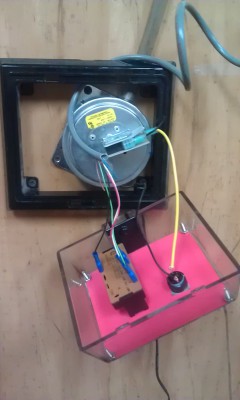
We have a Hack Rack full of junk and I know there’s this old bunch of gas furnace parts. It couldn’t be that easy…

LCEC02

Yeah. So, three days (and a few frustrating epiphanies) later, this all came together. Press the beige button, get some air. Press the other buttons, get some more air. Any time there’s suction, the red light comes on. The indicator light is powered by its own 24 volt DC wall pack. The pressure switch has both normally open (N.O.) and normally closed (N.C.) contacts so it would be totally feasible to add another light at some point. The controller could display “OFF” or “SAFE” or whatever as well as “ON” or “FAN IN USE” or whatever. The text is just a red piece of paper with words printed on it, then holes laser-cut out to fit. We can trade it out with different words or graphics if we ever feel the need. I was just glad to have it done, so I called it. Better is the enemy of done, indeed.

LCEC03

You can learn more about the evolution of our laser cutter venting system on our wiki!