Updated Filament Spool Holder for SoM

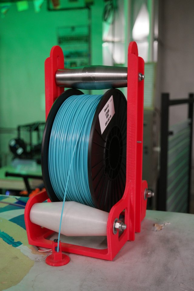
Big thanks to Tom Klein for a great modification of SoM’s filament spool holder!

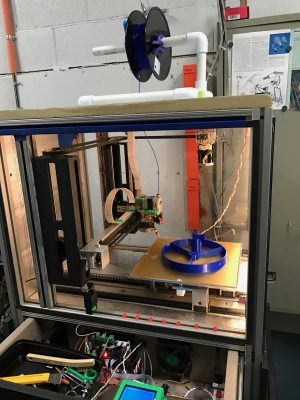
The original design used to have a printed ABS top roller and I just pushed the roller against the flanges and finger-tightened the nut.  The problem was people kept taking it apart, so I added rubber bands to pull the roller down, and a nylock nut to prevent tool-free disassembly.  Then the rubber bands kept disappearing, and Tom came up with the idea of making a heavy top roller so the rubber bands wouldn’t be needed.  He cut a new, steel top roller on the lathe and it works great!  The bolt is just loose enough to let the roller slide up and down in the slot in the frame.  The roller is heavy enough that it just falls into position on the spool flanges.

Tangle-free filament spool holder

We have a new Prusa i3 Mk3 3D printer!

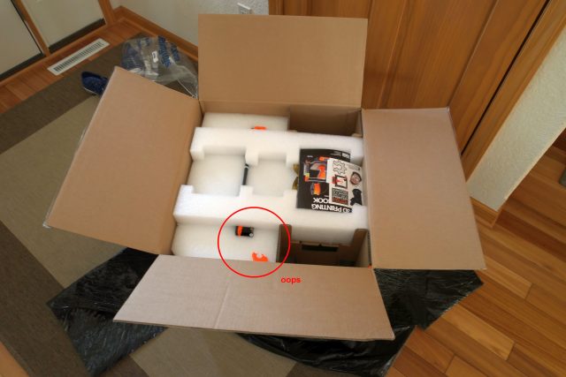
This is the printer that we won in the Hack-a-Day contest about 2 months ago.  It arrived at my house last night, so I decided to open it up and inspect the contents.  That’s when I saw it…

Broken upper left Z axis guide rail bracket.

Broken upper left Z axis guide rail bracket!

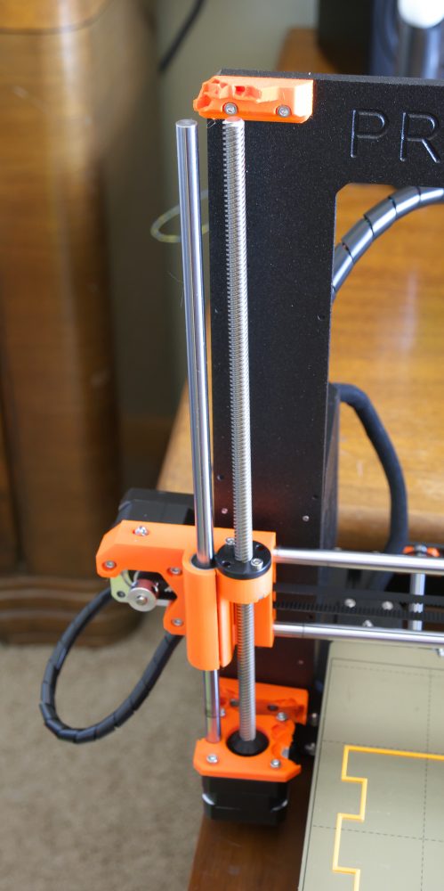
I lifted it out of the box and discovered that the left Z axis motor mount was also broken:

Broken upper left guide rail clamp and left Z motor mount.

Broken upper left guide rail bracket and left Z motor mount.


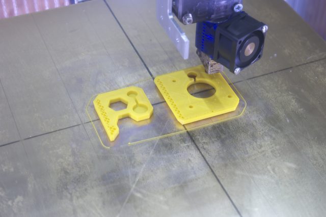
A quick trip to the Prusa web site found STL files ready for printing…


New motor mount and upper left guide rail clamp printing on UMMD.

New motor mount and upper left guide rail clamp printing on UMMD.

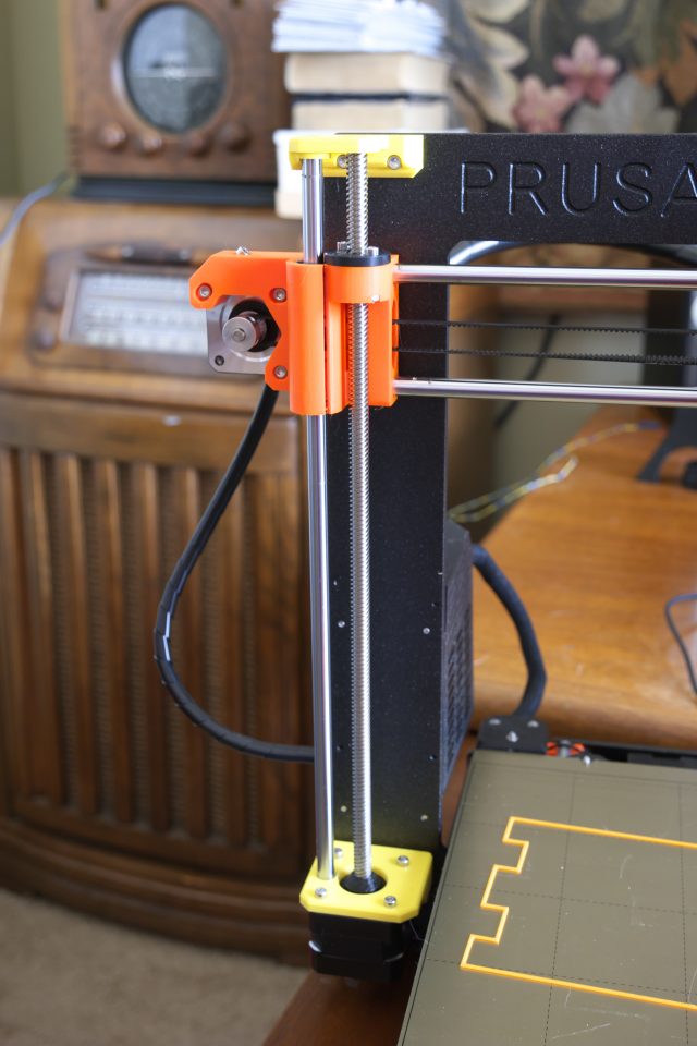
Finally, printed parts installed…

Broken parts replaced.

Broken parts replaced.


Alas, it appears that the lead screw is bent- you can see it wobbling when it rotates.  I’ll be contacting Mr. Prusa for a replacement…

Fun in the Booth at the Milwaukee Maker Faire

Last minute decisions work out once in a while.  For example, I was going to be at the Makerspace booth at the Milwaukee Maker Faire for the weekend and wanted some examples of the sorts of things you can use a 3D printer to make, so I grabbed the usual collection of sample prints, and then I thought, “sure, why not?”, and loaded the Van de Graaff generator into the car.  It sat on the floor in the booth for about 1/2 of Saturday and I was getting a little bored, so I moved it closer to the foot traffic and plugged it in.  Wow!  Kids and adults with stunted emotional development went nutz!  They were zapping themselves and each other as if it were more fun than painful.
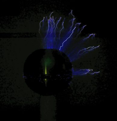
Sparks!

Sparks!  The VDG produces about 400 kV.

Then I found a plastic bucket and the fun really started.  We had kids and many adults who were definitely much too heavy, standing on the bucket and making their hair stand up with moms, dads, boyfriends, girlfriends, husbands, wives, partners all taking pictures.   I had to move one gentleman who was breathing oxygen from a tank away from the machine.  Fortunately, no one fell off the bucket or caught on fire, and next year we’ll do it right and take a block of styrofoam for people to fall off of  to stand on.
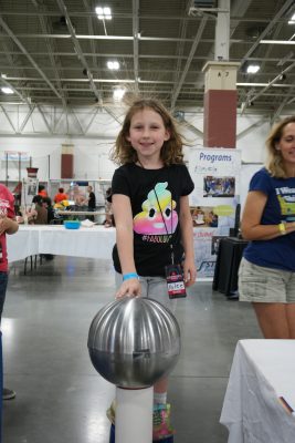
Kylee was ready to join the Makerspace just for this… and with that shirt, she’d fit right in!
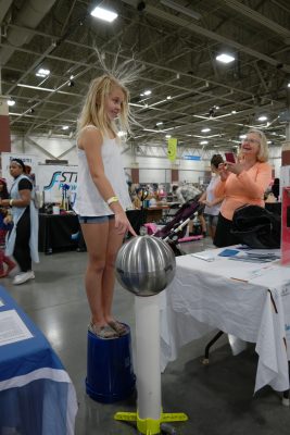
 

Blondes really do have more fun!

Blondes really do have more fun!

Even Gordon couldn't resist!

Even Gordon couldn’t resist!


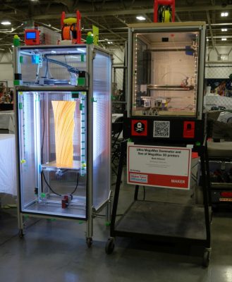
Last year Son of MegaMax (a 3D printer built at the Milwaukee Makerspace) went to the Faire.  This year he had two companions to keep him company- an extra-beefy printer being built by Erich Zeimantz: MiniMax XY.  MMXY isn’t complete yet, but promises to be a super high quality, high speed printer.  He’ll be operational at next year’s Maker Faire.  SoM also brought his big brother, Ultra MegaMax Dominator, named that because he is ultra, mega, maximum, and he dominates.
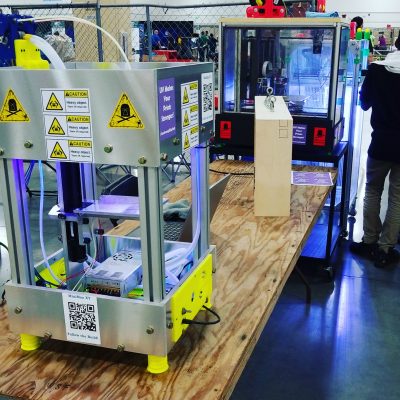
MiniMax XY at Milwaukee Maker Faire
MiniMax XY at Milwaukee Maker Faire


Ultra MegaMax Dominator and Son of MegaMax at the Milwaukee Maker Faire

Ultra MegaMax Dominator and Son of MegaMax at the Milwaukee Maker Faire

UMMD and SoM rotated between the booth and the dark room where the both printers’ UV lighting and fluorescent filament was a big hit.
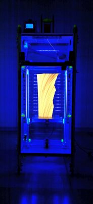
UMMD in the Dark Room at Milwaukee Maker Faire 2017

UMMD in the Dark Room at Milwaukee Maker Faire 2017

We had a few things besides 3D printers at the booth.  Tony brought in some Bismuth crystals to give away, and surprisingly, they didn’t all disappear in the first hour.  Tony thinks people left them because the Makerspace logo on the info board on which the crystals were sitting looked a lot like the skull and crossbones that usually indicates poison.  The crystals do have an other-worldly toxic look about them.  Oh well…
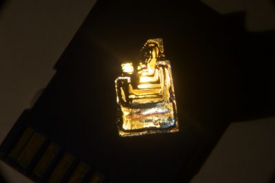
Bismuth Crystal

Bismuth Crystal

Marcin’s LED signs on the table at the booth and hanging above the entrance to the Dark Room were also very popular and hard to miss, though I managed not to take any pictures of either.  The one above the Dark Room was so bright that if you saw it, you’ve probably still got its image burned into your retinas.

Everyone involved had a great time and we’ll be there again next year with even more cool stuff!


3D Printed Telescope Spider

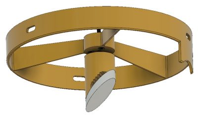
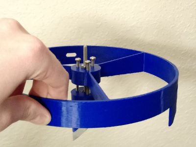
I am designing and building a homemade telescope, loosely following designs from here. While a lot of their components are ingeniously designed, I wasn’t satisfied with the spider plans they provided. I decided to try my hand at designing my own spider in Fusion 360 (using their free enthusiast subscription) and 3D printing it.

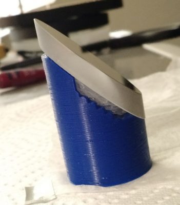
The spider snugly fits in an 8″ diameter tube. There are 3 slots in the perimeter to allow rotational alignment along the axis of the tube. There are 3 additional screws in the central cylinder that tilt the diagonal mirror holder and provided height adjustment. The diagonal holder has multiple grooves to provide more surface area for the silicone to bond to. The surface the mirror mounts on is on a 45. The entire thing was printed in PLA on Mark’s SOM printer (huge thanks to Mark for helping out).
A similar design could be constructed in the machine shop with multiple operations and perhaps even some welding, but the ease of designing this in Fusion 360 along with the little setup involved in the 3D printing process made this an ideal path to choose.

Replacing the Glass Print Bed on the Taz 3 Printer

The glass bed on the Makerspace’s Taz 3 printer recently did what glass does- it broke.  Time for a repair and upgrade!

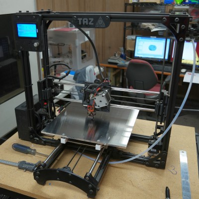
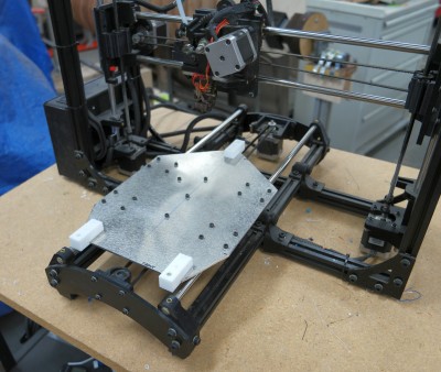
I started by cutting the under carriage down and modifying it for a three point leveling system instead of the stock four point undercarriage/bed plate bending scheme.

Modified undercarriage mounted on the printer

Modified undercarriage mounted on the printer


The original heater was separated from the shards of glass and glued to the 12″ x 12″ x 1/4″ cast aluminum tooling plate using high temperature silicone.  3x #10 countersunk screws and springs support the plate on heat resistant teflon blocks.  The whole assembly stands about 1 cm taller than the original bed plate so I printed a small extension for the Z=0 set screw so it would trip the switch from the higher position.  I tested the heating time and found that the bed gets up to 110C in about 16 minutes- a little slow, but we probably won’t be printing much ABS with this open frame machine anyway.  Next- run PID autotune for the bed heater and adjust acceleration (greater moving mass means lower acceleration and print speeds).

New bed plate and undercarriage mounted on the printer

New bed plate and undercarriage mounted on the printer


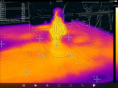
Some of you might ask why I would replace the glass bed with a piece of cast aluminum tooling plate.  Thermal performance is one good reason.  Here’s an IR photo of the original glass bed:


Taz_glass_thermal

IR image of the Taz 3 printer with original glass bed.


Notice the hot and cool spots- 30C temperature variation across the bed.

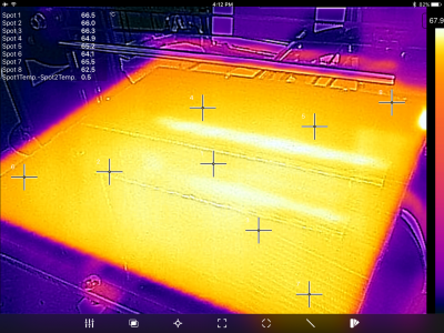
Here’s what the new aluminum bed plate looks like:


Taz_aluminum_Thermal


Temperature variation is just a few degrees over the entire surface (the bright almost horizontal lines are not hot spots- they are reflections of the X axis guide rails).


I have run the PID tuning on the new bed and modified the firmware with the new constants.  It heats from 25C to 100C in about 9 minutes.

I officially declare the Taz printer ready for action.