Rube Goldberg DoorBell Lives

rubegoldberddoorbelllives

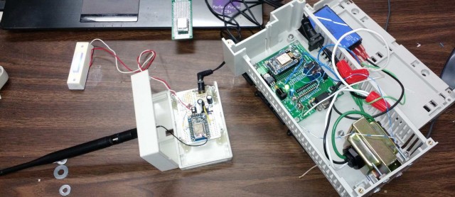
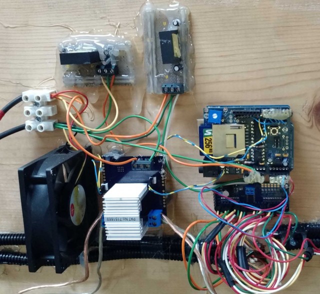
I finally got my rube goldberg doorbell into an installable state. On the left is the door button detector. It is an ESP8266 ESP-07 making use of the U.FL connector to allow the WiFi signal to punch through from my basement to the 2nd floor where the router is located. On the right is another ESP8266 and a doorbell transformer. Just barely peaking out from under that module is an actual doorbell.

A key aspect of the system is that the door button module doesn’t communicate directly with the door bell module. Both modules log into a Mosquitto MQTT broker. The button module “publishes” events on the MQTT topic of “DoorBell” and the bell module subscribes to the MQTT topic of DoorBell. Later, I can split the topic names and have something like OpenHAB conditionally copy events from one topic to the other depending on the time of day. OpenHAB can also translate MQTT events to a service like Notify My Android so that my phone buzzes in response to a door button push.

I am excited to install this at home and see how it does!
ATSAMD21J Test

Recently Arduino came out with the Arduino Zero. This is a neat 48MHz ARM Cortex M0 processor on a PCB with the same pin outs as an Arduino UNO. Existing 3rd party UNO libraries are a little hit and miss because some access the underlying hardware registers of the UNO. The Zero hardware registers are completely different from UNO. Still, the basic 1st party Arduino libraries work fine and I’m sure those 3rd party libraries that were twiddling the UNO hardware registers directly will start to support the Zero over time.

Anway, my curiosity was peaked by the ARM processor for the Zero the Atmel ATSAMD21G18. It turns out that the processor has alternative packages with higher pin counts. Same silicon, just more pins. So I gave the ATSAMD21J18 a try. In order to be able to use extra pins with digitalWrite, I had to add a small amount of code to a file called variant.cpp, but once done, I had a Zero with a nice chunk of extra I/O capability.

Continue reading

Refreshing the Singing Pumpkin Display

I’m getting my original singing pumpkin display ready for BVNA’s Pumpkin Pavilion and Halloween. The original display was pure prototype electronics consisting a bunch of stuff from Adafruit: an UNO, a Wave Shield, a PWM/Servo driver, and servos. There was a footprint challenged custom PCB for a TDA7297 and some junk bin DC-DC convertors.

OldController

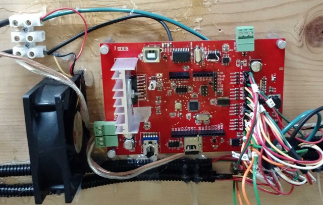
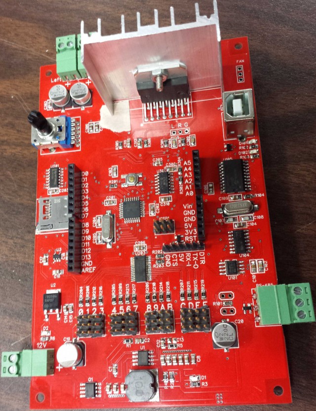
It didn’t look pretty, but it did the job for years. However, the new fully integrated prototype controller looks a lot snazzier.

NewController

There are still more design changes to come for this board, but it was really nice to see it perform as intended in my full display.

Singing Pumpkin Commercial

SingingPumpkinCommercial

The Singing Pumpkin controller continues along. This new spin of the board corrects the previous flub-up of the reversed amplifier pin-out as well as adds USB and RS-485 to the mix. There are some minor errors on the board, but nothing that has prevented 90% of the board function from being validated. I need to check the recv direction on the USB, the Arduino-style reset pulse, and the RS-485 transceiver. With that I’ll be able to work on generalized firmware and PC software.

1MHz DC-DC Converter Test

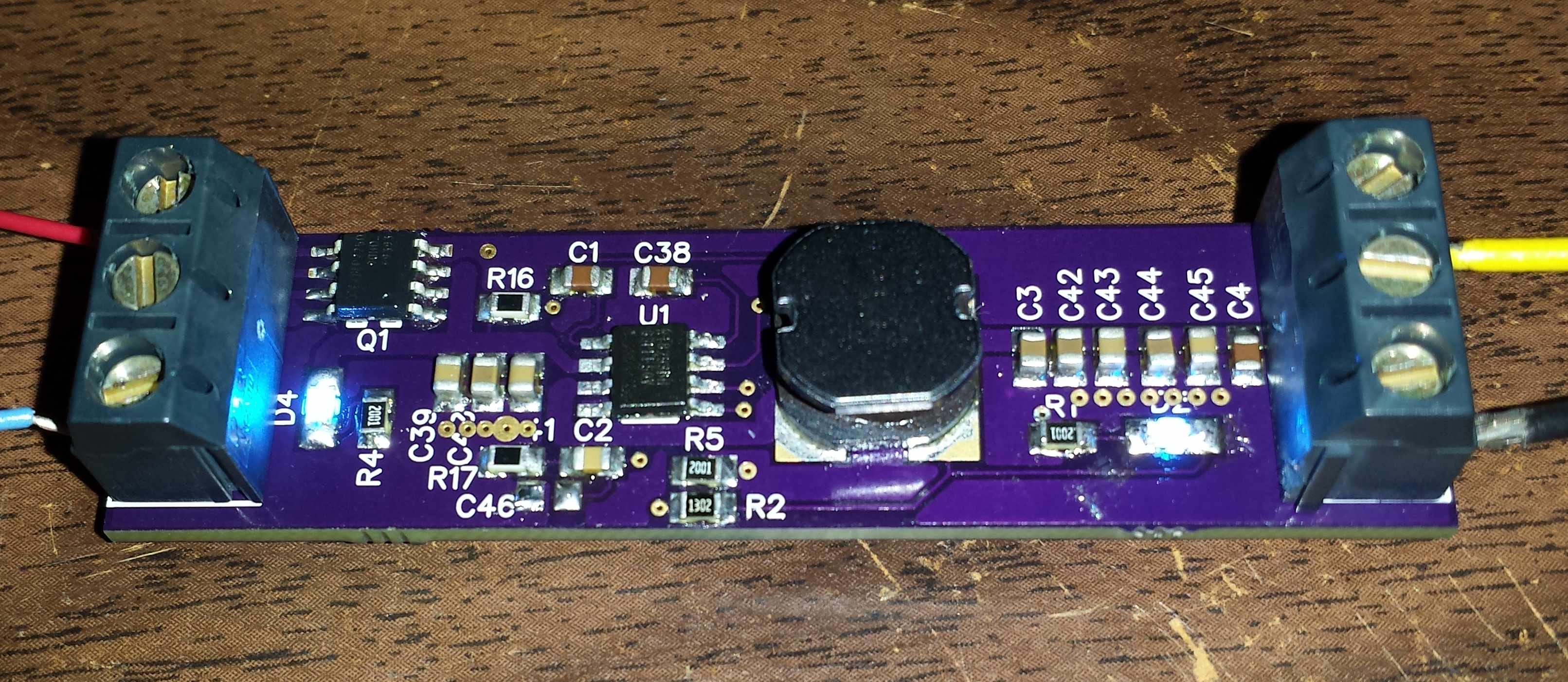
dcdc1mhzThis week I tried out a new DC-DC converter, the RT8293BHGSP, for my singing pumpkin controller. The issue I had with the old converter was that it was pretty expensive to get a 100uH coil that was rated for 4 or 5 amps. The most recent spin of the board only has about a 1.5 amp coil on it. This new converter runs at a little over 1Mhz as opposed to ~300kHz for the old converter. As such it can use a much lower value coil (10uH) that can be obtained in the 4 to 5 amp range for a reasonable price and with a reasonable package size.

This tester board seemed to work pretty well. It got plenty warm pushing around 2 amps, so it may need a heat sink. Still I’m pleased to have a solution that lets me get all the way up to the 3 amp limit of the converter.