If anyone has aluminum that you would be willing to donate to our aluminum pour please bring to maker space, drop off in foundry area and notify me!
The foundry Gods thank you.
Kayla Schroeder
414.429.1731
Be a part of a hacker/builder community where ideas are shared, innovation is fostered and the maker experience is hands-on.
Join us Tour the SpaceIf anyone has aluminum that you would be willing to donate to our aluminum pour please bring to maker space, drop off in foundry area and notify me!
The foundry Gods thank you.
Kayla Schroeder
414.429.1731
Chocolate printer progress continues. This week was devoted to the print cooling system. The chocolate will come out the extruder nozzle in a semi-molten state. It needs to solidify by the time the next layer of chocolate gets deposited on it, and I’d prefer it doesn’t drip or sag, so it needs to be chilled right after extrusion. The current plan is to blow chilled air over the chocolate just after it leaves the extruder. The chilled air will come from a foam insulated box containing a block of dry ice. There will be a blower pushing air into the box and a hose delivering the chilled air/CO2 to the print.
A couple weeks ago I got a blower from American Science and Surplus and this week I got it running by using a model airplane ESC and servo tester to drive its brushless DC motor. It appears to be capable of blowing much more air than I’ll need. There are many unknowns yet to test. How much chilled air/CO2 will it take to solidify the chocolate after it leaves the extruder? How long will a block of dry ice last when used this way? Will ice build-up inside the chiller box adversely affect its performance?
I designed and printed three parts for this system- a mount to attach the blower to a foam box up to 1.5″ thick, a hose coupler to allow delivery of the chilled air/CO2 to the print, and a hole saw to cut holes to fit the other two parts. The printed parts fit as if they were designed for the job!
My last post showed how I made a plunger for a 3.5 liter syringe. Today’s post is the results of the first ever test of that syringe assembly including the plunger. The goal of the test was to determine if the syringe pusher would be able to push very thick, viscous paste (sort of like melted chocolate) out of the 1/4″ syringe nozzle. It was also a test of the ability of the previously made silicone plunger to maintain a seal even against whatever pressure develops inside the syringe as it is pushing.
I mixed about 1 liter of extra thick pancake batter to a consistency that I thought would be much thicker than molten chocolate (pancake batter is much cheaper than chocolate) and shoveled it into the syringe, then bolted on the pusher and hooked it up to a power supply:
Looking back, I probably should have loaded the syringe from the other end.
Here’s the actual test. It gets especially interesting about 1 minute in:
The syringe continued drooling after power was removed due to air that was trapped inside the syringe. As the plunger pushed, the air was compressed. When the motor stopped the compressed air continued to push out the batter. I will have to be careful to eliminate air bubbles in the material when it comes time to use this in a printer.
It only took a couple minutes to clean out the syringe after the test was done.
The pusher did its job much better than expected, and the plunger held up just fine, too. I feel confident that this device will be able to extrude chocolate. Now the real work begins…
My latest project is a 3D printer that will produce chocolate objects. Like many other chocolate printers, it will include a syringe to dispense the chocolate. Unlike those other printers, the syringe in my printer will have 3.5 liter capacity to enable printing large objects.
The syringe is made from PVC pipe using mostly standard fittings. One piece that wasn’t standard was the plunger that fits inside the syringe tube and pushes on the chocolate contained therein. I had to design and fabricate the plunger. PVC pipe isn’t perfectly smooth or perfectly round inside, so I needed something compliant enough to ride out the pipe’s bumps and constrictions while maintaining a seal. The seal needed to be tough, yet safe for use with food because it will be in contact with the chocolate inside the syringe. I found some food-grade silicone casting material and ordered it.
While waiting for the silicone to arrive, I designed a 3D printable core for the plunger and a mold and jig. The core fits on the end of a linear actuator that will provide the push. The jig centered the core a few mm above the bottom of the mold. The mold was tapered and the widest part -the bottom- was a few mm larger diameter than the pipe, and several mm larger diameter than the core. The silicone envelops the core and is locked in place by holes that connect top and bottom side of the core. The plunger squeeze-fits into the pipe to maintain the seal against the uneven inner surface of the pipe.
I measured and mixed the silicone, coated the core with it and then set the core and jig in/on the mold and let it cure for 24 hours. Then I removed the jig and broke the now silicone covered core out of the mold. Result: a perfect, tight fit inside the syringe tube.
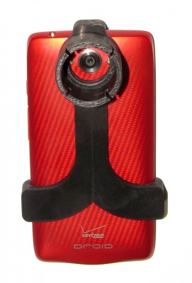
After successfully mating a web cam with my microscopes (http://www.thingiverse.com/thing:216821) and telescope (https://www.youmagine.com/designs/web-cam-adapter-for-meade-telescope-eyepiece), I decided to design and print adapters to mount my Droid Turbo phone on the same scopes (https://www.youmagine.com/designs/microscope-adapter-for-droid-turbo-phone and https://www.youmagine.com/designs/droid-turbo-phone-to-telescope-adapter) so I could shoot higher resolution stills (21 Mp) and 1080p (and even 4k) video. The telescope adapter fits over a Meade 32mm focal length Super Plössl eyepiece and provides about 47X magnification with the telescope. I printed a similar adapter for my surgical microscope.

The telescope adapter firmly grips the phone and the eyepiece.
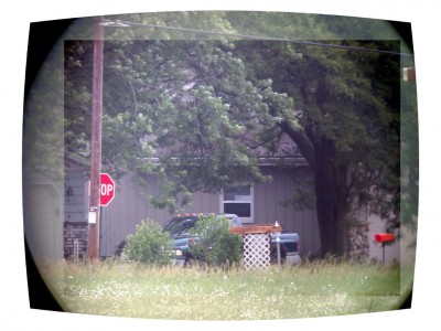
Initial tests were a little disappointing. The combination of the phone’s camera and the telescope’s optics has significant pincushion distortion. The image has only been mirrored L-R and scaled down (original is 21 Mp). Note the lack of contrast (looking through 1/2 mile of humid air) and the curves in the power line and pole, and even the grass line:
A quick search found that the Gimp has built in transform tools to correct (or create) lens distortion.
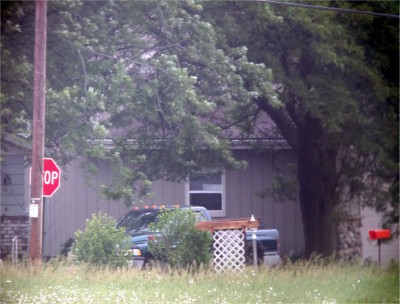
It only took a couple minutes of messing around to get acceptable results. Here’s the same image with the pincushion distortion corrected (whole image), contrast stretched and white balance corrected (rectangular area). The pole, power line, and even the grass line now look straight.

And here’s the final image with all corrections and cropping applied:

Next step: photograph known square grids through the microscope and telescope and then create and save some preset corrections to apply with Gimp.
I wonder if something like this exists for video. Hmmmmm…