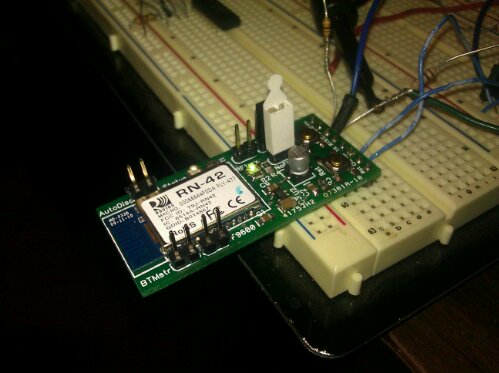
I got that RN-42 carrier board populated and working! Its ready for the GyroSkirt driver board, once I get that built.
There are a few errors on the board. TX and RX are swapped somewhere. Either on this board or on my USB to TTL-Serial board or in the RN-42 documentation. Also it seems the LEDs were meant to go to Vcc rather than ground. As a result my LED indication for connection status and RF traffic is inverted.
I can live with the errors as the actual data transmission works like a champ. To test the tranmission I hooked the carrier board up to a PC via a USB to TTL serial converter configured to operate at 3.3V. The venerable Hyperterminal program was used to open the virtual com port on the PC. Then I downloaded Sena’s Bluetooth terminal program to my Android phone and used it to form a Bluetooth serial connection between my phone and the modem. The result: keys pressed on my phone’s keyboard appeared inside the Hyperterminal running on the PC and keys pressed on the PC keyboard appear inside the Sena Bluetooth terminal running on my phone. Bi-directional data flow at 115,200 baud.
Now that I have proven my wireless link works, I need to update the GyroSkirt/GryoBelt firmware to allow me to adjust the gain and the deadband over the Arduino’s serial port. (In addition to actually making a driver board that has a spot for the modem.)
Hello Royce,
I have bought an RN-42 module and I am having some problems with it in serial communication with ATmega8. The module connects okay & status LEDs also lit when there is an established connection. Even the null modem connection works fine when I connect the RX to TX of RN-42 together and the characters are echoed back on the terminal on my laptop.
I have even brought down ATmega’s supply to 3.3v so that there is no need for 5-3.3 logic conversion. But still it seems to take it all as garbage!
So I wanted to just ask whether the Rx-Tx logic is inverted from RN-42. It doesn’t tell anything on this in RN-42 datasheet.
I have yet to connect the RN-42 to an MCU, the GyroSkirt project has been on the back burner lately. I did notice that RX-TX were flipped somewhere in the chain but I am not certain that it was at the RN-42.
My recommendation is to get a FTDI USB-Serial convertor set for 3.3V operation. (Adafruit and Sparkfun sell them) Connect only the RX and GND lines of the FTDI to the RN-42’s TX and GND lines, respectively. Then run two instances of hyperterminal or some other terminal. Connect one to the RN-42 via BT, connect the other to the FTDI USB Comm port. Try to get characters from one terminal to the other. If the character don’t appear or are garbage try changing the connection between the FTDI and RN-42 from RX-TX to RX-RX.
The overall point is that it is much easier to experiment and verify settings using two terminals than it is to keep reprogramming the Atmega8.
If you get the terminals working but the Atmega8 still doesn’t work, make sure of your UART settings and make sure you are using a crystal for accurate serial timing.
Thanks for your kind reply :)
Yes that’s very logical thing to communicate between the terminals. But why I went for AVR is because I had to ultimately use it with AVR only & it can run off 3.3v. I unfortunately do not have the FTDI chip and using a USB-serial converter cable together with MAX232 to get 5V Rx-Tx TTL signals. I set up the AVR to display received data on an LCD & transmit a test string every sec. Later when I suspected the internal RC oscillator, I even put the 16M crystal for ATmega’s clock. But all to no avail since all I get on LCD is garbage :/
My AVR code for serial comm is well tested and it runs fine otherwise. What puzzles me is that even if the AVR is at 5V, it should accept 3V as a valid high at its Rx input.
So I have done quite a no. of tests since then. I had put an LED from RN-42’s Tx to VCC (with 1K resistor) so that the Tx pin sinks current. So there it was, the LED blinked faintly while receiving data, which shows indeed the data is coming. Then I even tried to buffer it with 2 daisy-chained gates of CD4069 @5V which then go to Rx of AVR @5V. Still nothing. The LED glows more strongly after the buffers, as is expected. Then, after the buffer, I put the other terminal, Max232 with my USB-serial to hopefully receive something meaningful. But still garbage on the other terminal!!!
So ultimately I guess I’d have to use a scope to find what the heck is happening really. Who knows if cosmic interference or something alike is the culprit ;-)